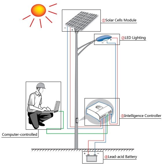
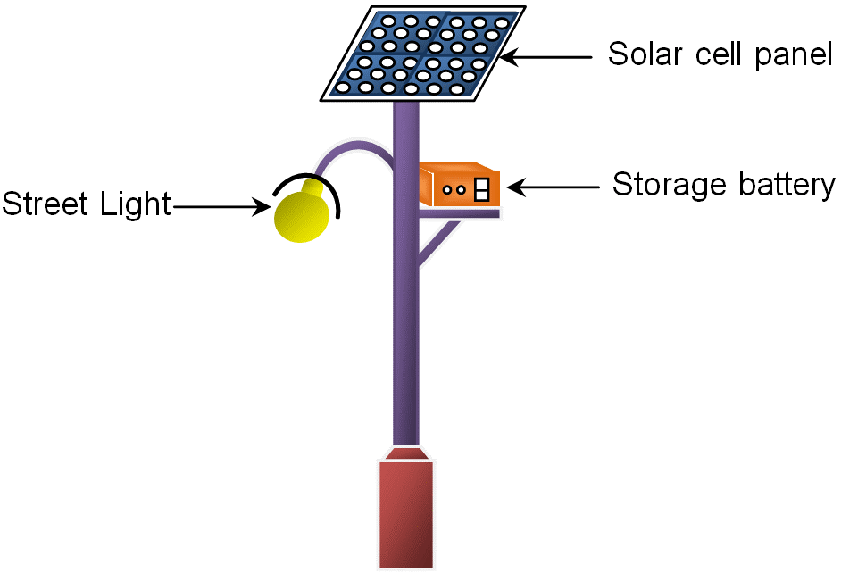
Solar street lights with is Components and Working Principle
In this video, I have explained the street light wiring connection. Here this circuit can be operated manually and automatically. The electric timer is used.
How Exactly Does a Solar LED Street Light Work? TACHYON Light
Street light wiring connection is an essential part of the installation and maintenance process for street lighting systems. It involves connecting the various components of the street light system, such as the lamp, ballast, photocell, and power supply, in a safe and efficient manner. A well-executed wiring connection ensures that the street.

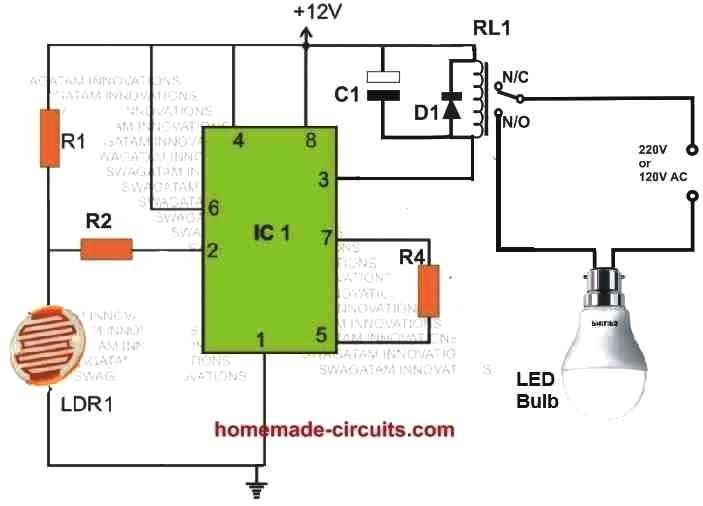
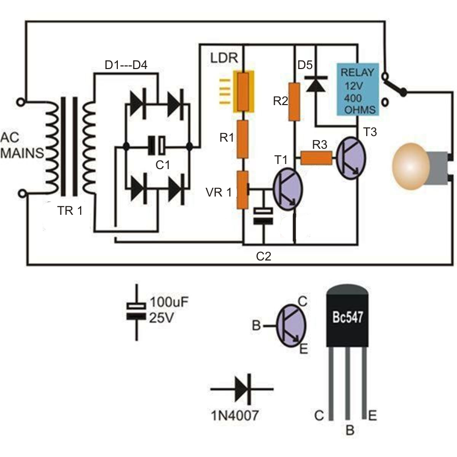
Simple Automatic Street Light Circuit Diagram with LDR
Simplest DC Motor Ever. Advantages: The automatic operation of street light controlling systems help to reduce the energy consumption as compared to the manually operated street light controlling operations. This is because there is a delay in the earlier switching operations both in morning (during sunrise) and evening (during sunset).

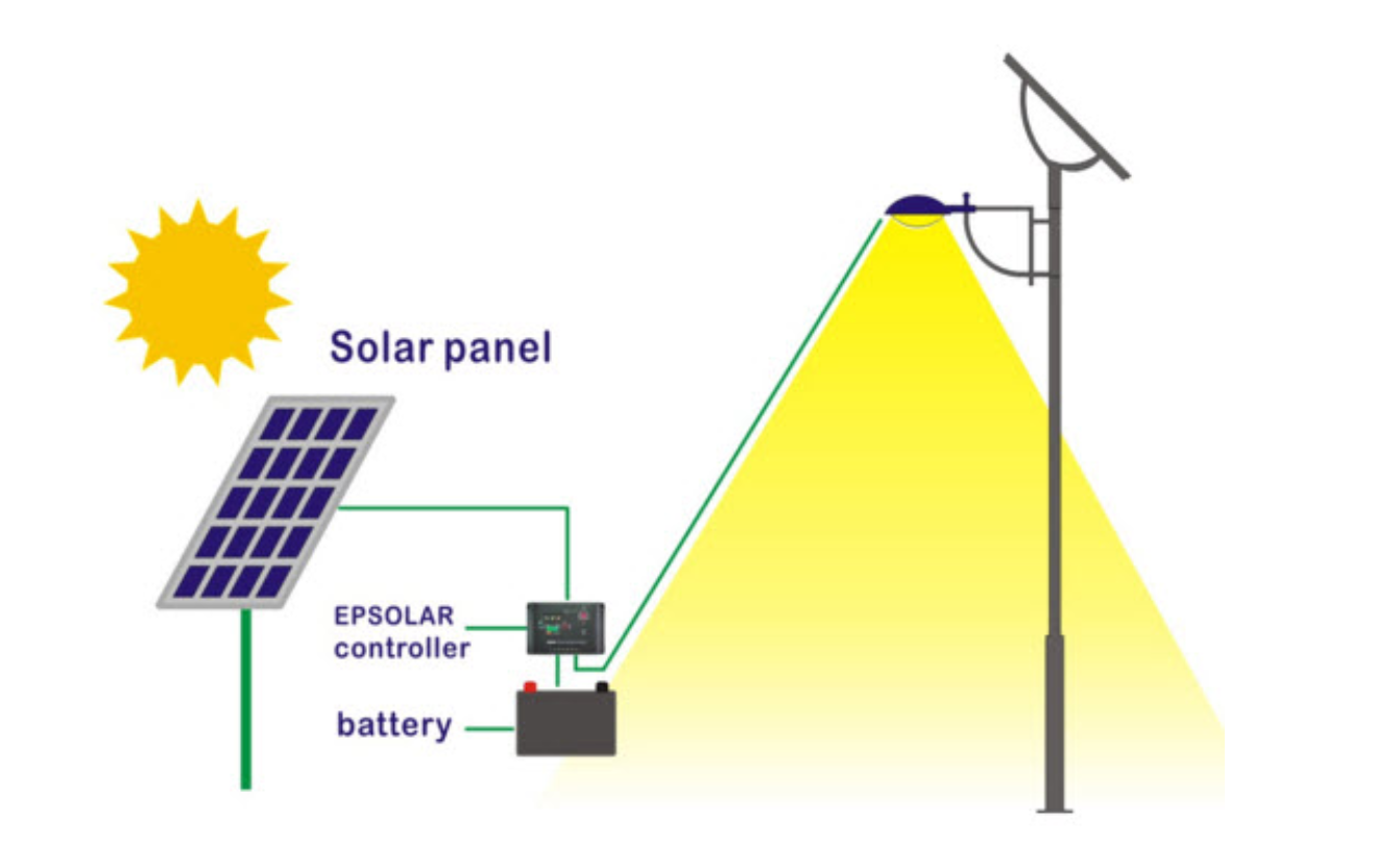
Solar Street Light Connection Diagram
CAUTION: A charge controller is a must for any street light system. You may find other designs on the internet without this feature, simply ignore them. Those can be dangerous for the battery! Referring to the 40 watt street light circuit diagram above, the panel voltage is regulated and stabilized to the required 14.4 volts by the IC LM 338.
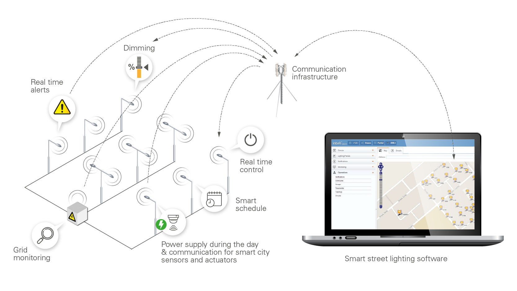
Everything you need to know about Smart Street Lighting inteliLIGHT®
Arduino Smart Street Light System Project Circuit Diagram Working Principle. An LDR is connected to the analog pin of the Arduino. It controls the LEDs by detecting the presence or absence of sunlight. When sufficient sunlight is present in the surroundings, then the LDR offers high resistance and acts as an insulator. In this case, the Arduino.
6 Automatic Street Light Circuits [Using Relays and Solar Panel
The street lighting system layout should generally be as shown in Detail SL-01. Facilities are normally located in the grass utility strip between curb and sidewalk. Wiring is to be underground, in conduit, with an underground junction box at each light installation. Luminaries (light fixtures) are to be 120-Voltand individual
Solar Street Lights Mesar Energy
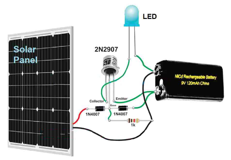
Step 1: Circuit Diagram This is the diagram of the circuit we are going to build Ask Question Step 2: Collect All the Parts Collect all the parts required for the circuit as per the diagram in the previous step. All of these should be available from any electronics supply store. Match the colour bands in the registers carefully. Here are the parts:
Simple Automatic Street Light System
Assisting in the protection of buildings/property (discouraging vandalism) Discouraging crime Creating a secure environment for habitation Basic Features of Street Light Luminaires The basic features of a street lighting luminaires are: Roadway luminaires are mounted horizontally and thus have fixed vertical aiming.

street light pole wiring diagram AshlieLoulou
Switch L.D.R (Light Depending Resistance) I.C NE555 with Base L.E.D (Light Emitting Diode) 5 pieces. (If using white color then 4 Pcs) Variable Resistance of 47 KΩ P.C.B (Printed Circuit Board of 555 or Vero board. Circuit Diagram of Automatic Street Light COMPONENTS :
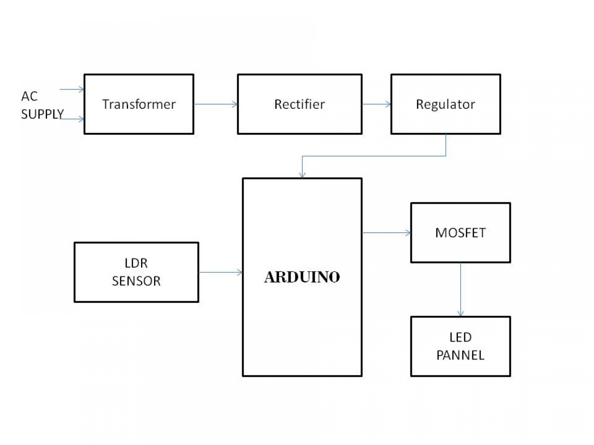
INTENSITY CONTROL OF STREET LIGHT USING LDR AND ARDUINO Electrosal
Arduino Smart Street Light Project Code Explanation: This command will define the IR sensor which is connected with the digital pin 2 and digital pin 3 of the arduino. 1. 2. 3. int IR1 = 2; int IR2 = 3; This command will define the LEDs which are connected with the digital pin 5 and digital pin 6 of the arduino. 1.
automatic street light control system circuit diagram Wiring Diagram
The position of the street light poles shall conform to Standard Drawings 5-5A through 5-8. F. Street Lights on Existing Utility-Owned Poles -- Where there are permanent existing (or necessary planned) utility owned poles adjacent to the roadway, the street lights may be installed upon the utility pole in lieu of the required street light poles.

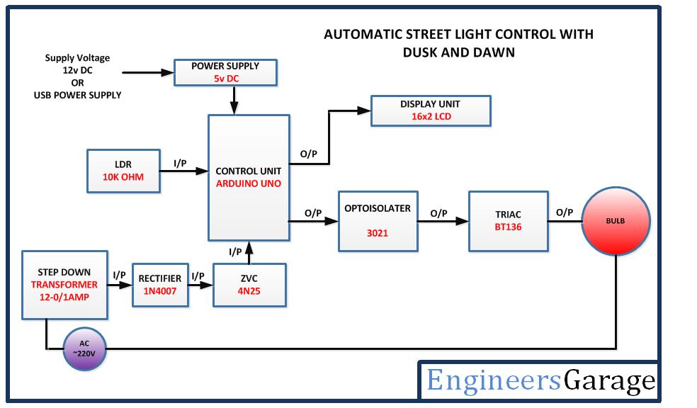
RTC Based Automatic Street Light Using Arduino & LDR
What is LDR? LDRs are made from semiconductor materials to enable them to have their light sensitive properties. There are many types but one material is popular and it is cadmium sulphide (CdS). These LDRs or PHOTO REISTORS works on the principle of "Photo Conductivity".
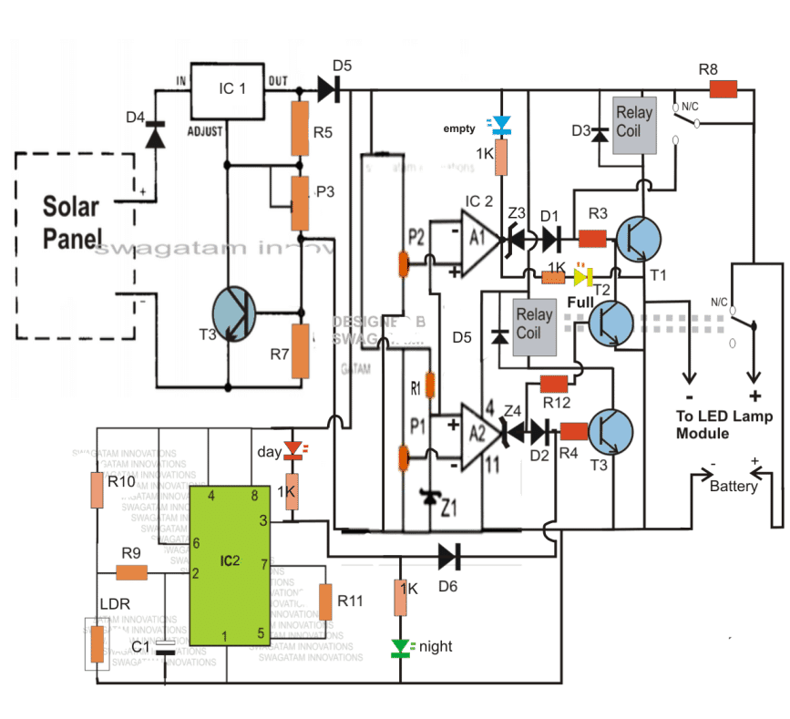
Automatic 40 Watt LED Solar Street Light Circuit Homemade Circuit
Street Light Wiring Diagram | An Overview by Charles Clark Updated on October 30, 2023 Streetlights are essential in order to ensure security, visibility, and beauty on the roads of both cities and the countryside. They're making the city prettier and helping to avoid accidents throughout the night.
Solar Led Street Light Circuit Diagram
Step 1 - Define the Area Needing Street Lights The first thing to determine is if a street requires street lights. The need for light can be because of accidents in the area along a roadway. It can also be because of a redevelopment project. A rural intersection may need street lighting because it is difficult to navigate at night.

41 Street Light Pole Wiring Diagram Wiring Diagram Source Online
Fig. 1 - Introduction to Smart Street Light System. The Internet of Things (IoT) primarily enables the concept of Smart Street Lights by collecting different types of electronic data from different physical devices using sensors and supplying information to the devices. By this, the expense spent on street lights can be significantly reduced and the amount saved can be invested in other.

Solar Street Lamp with Outdoor Roadway Lighting System Bingsolar Power
Description. The circuit diagram present here is that of a street light that automatically switches ON when the night falls and turns OFF when the sun rises.In fact you can this circuit for implementing any type of automatic night light. The circuit uses a Light Dependent Resistor (LDR) to sense the light .When there is light the resistance of LDR will be low.
